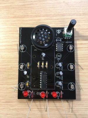
Schematic and build instructions for the PhotonTricoder Workshop PCB (v1.0-1.2)


Start with installing the three 100k mixing resistors.

Then add the three 100 ohm current limiting resistors.

Bend the legs of the six photocells to fit the footprint on the pcb.

Install photocells.

Add the two sockets for the ICs making sure to line up the notch with the graphic on the board.

Add the potentiometer by slightly straightening the side tabs and pushing with some force. If v1.1 note the potentiometer will operate backwards. V1.2 has this corrected.

Add the timing capacitors and audio coupling cap (C7). The three capacitors on the right are for the LFOs and can range from 10uF-100uF. The three on the left are for the audio oscillators and can range from 1uf – .1uf. These just suggestions, experiment! C5 is the speaker amp coupling cap and should be 100uF. C6 is a gain multiplier for the amp and is generally not needed.

Add the LEDs – you have two option: either insert them as indicated on the pcb graphic or orient so the cathode (shorter leg) is in the JP2/3/4 position. These control how the LFO signals modulate the audio rate oscillators. Before installing the speaker add the battery holder to the underside of the pcb. Solder the battery holder leads from the top then add the speaker with the + side towards the left. If v1.1 board you need to drill at least one hole in the battery holder to add the support screw.

