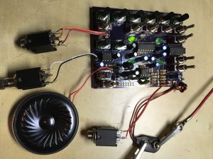
Building the Voice of Saturn Synthesizer mk II or, a great way to provide enjoyment for the whole family!
Welcome to v0.002 of the build guide for the Voice of Saturn Synthesizer mk II. Its going to be an exciting journey, so make sure you have the proper tools at hand!
- Needle nose pliars
- Wire snips
- Wire strippers
- A good soldering station with relatively fine tip (my personal fave is the Weller WES 51)
- Solder
- Solder sucker (we all make mistakes)
- Some wire – thin multi strand is best, like the stuff made into ribbon cables
- Beverage of choice
- Ambition!
If you ordered a parts kit first inspect the contents to ensure you have everything requires. IMPORTANT DOWNLOADS:
- Here is the bill of materials
- Here is the schematic
- Here is the parts overlay
- Here is the vector file for the panel design
It would be best to download the above and may be even helpful to print out at least the overlay and the BOM.
IMPORTANT
If you have the newer v1.2 board you can skip Step 7. If you are doing a build with the euro panel jump all 3 pads of the lower right speaker out switch and leave the switch off.
Step 0 – Resistors
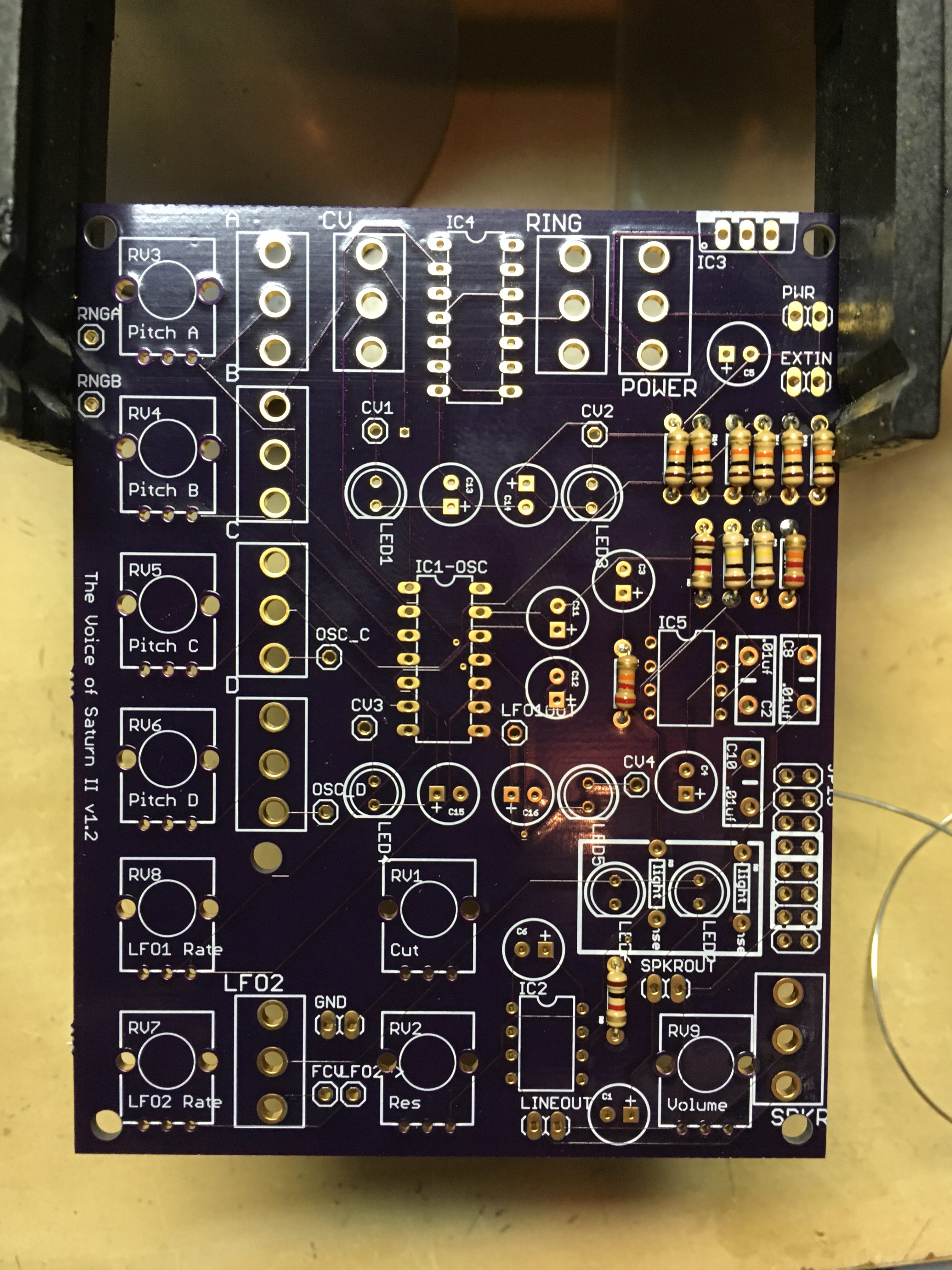
Solder in those resistors! You might find this resistor color code chart useful. Nothing particularly tricky here, just don’t mess with the resistors in the white box in the lower left of the PCB, we’ll cover those in just a bit.
Step 1 – Sockets
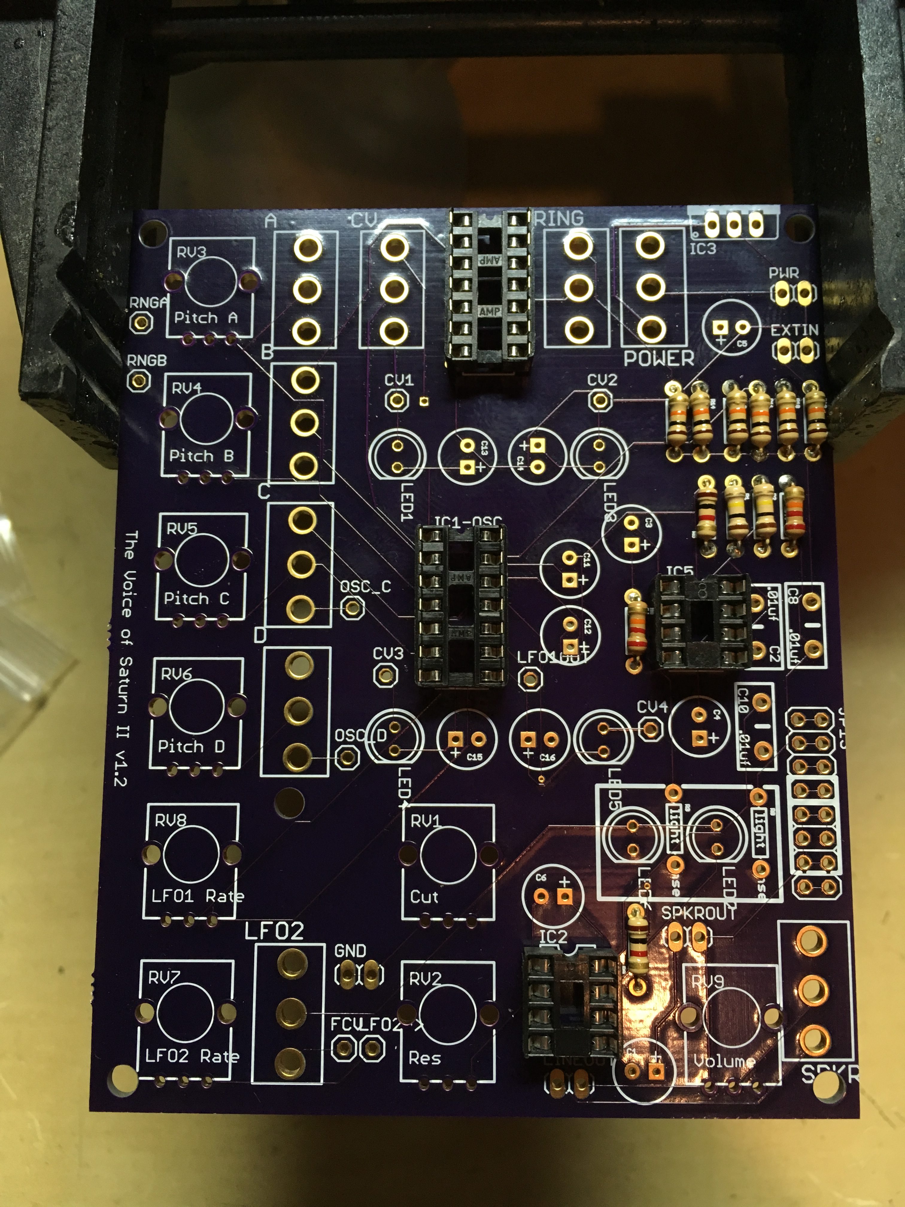
Then solder in the chip sockets but do not put in the chips.
Step 2 – Capacitors
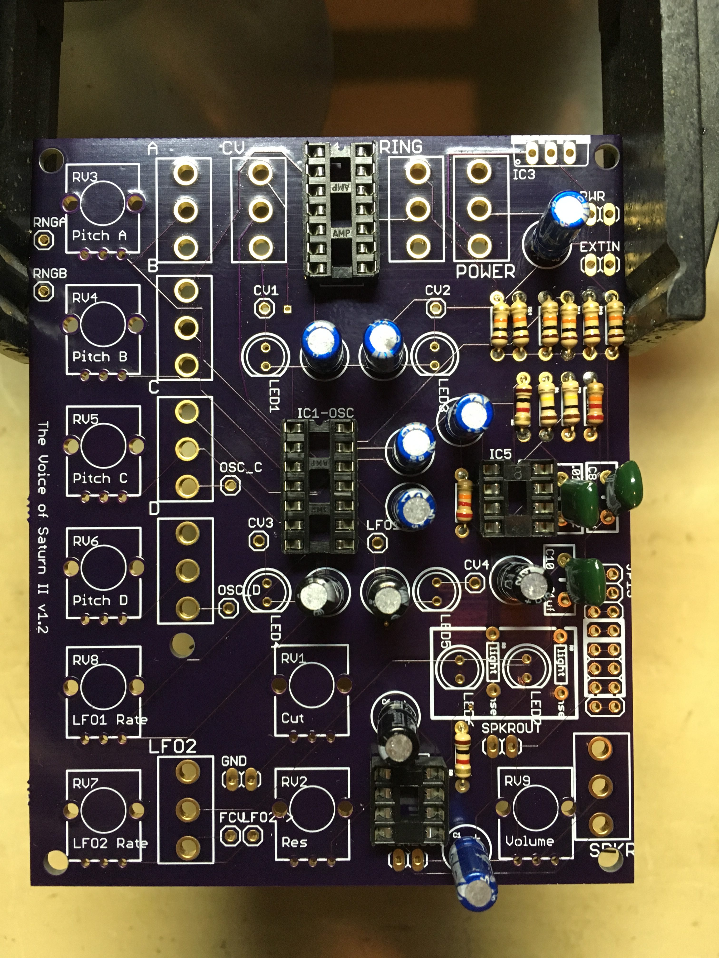
Followed by the capacitors. Nothing weird here but pay attention to the electrolytic caps and their polarity. The long lead is the + side, the – side is marked. If you look on the BOM you will see an asterisk next to C13-16. This means that the values can be changed if you want different oscillator ranges. 1uf for C15 and C16 seems to work best for use with the ring mod while 3.3uf for C13 and C14 give a bit lower rang for modulating each other. You can basically go anywhere from about 100uf – .01uf for different ranges. NOTE: C6 is optional. It increases the speaker output gain A LOT but also introduces more noise into the system. Include at your own risk, remove it if you don’t like it later!
Step 3 – LEDs
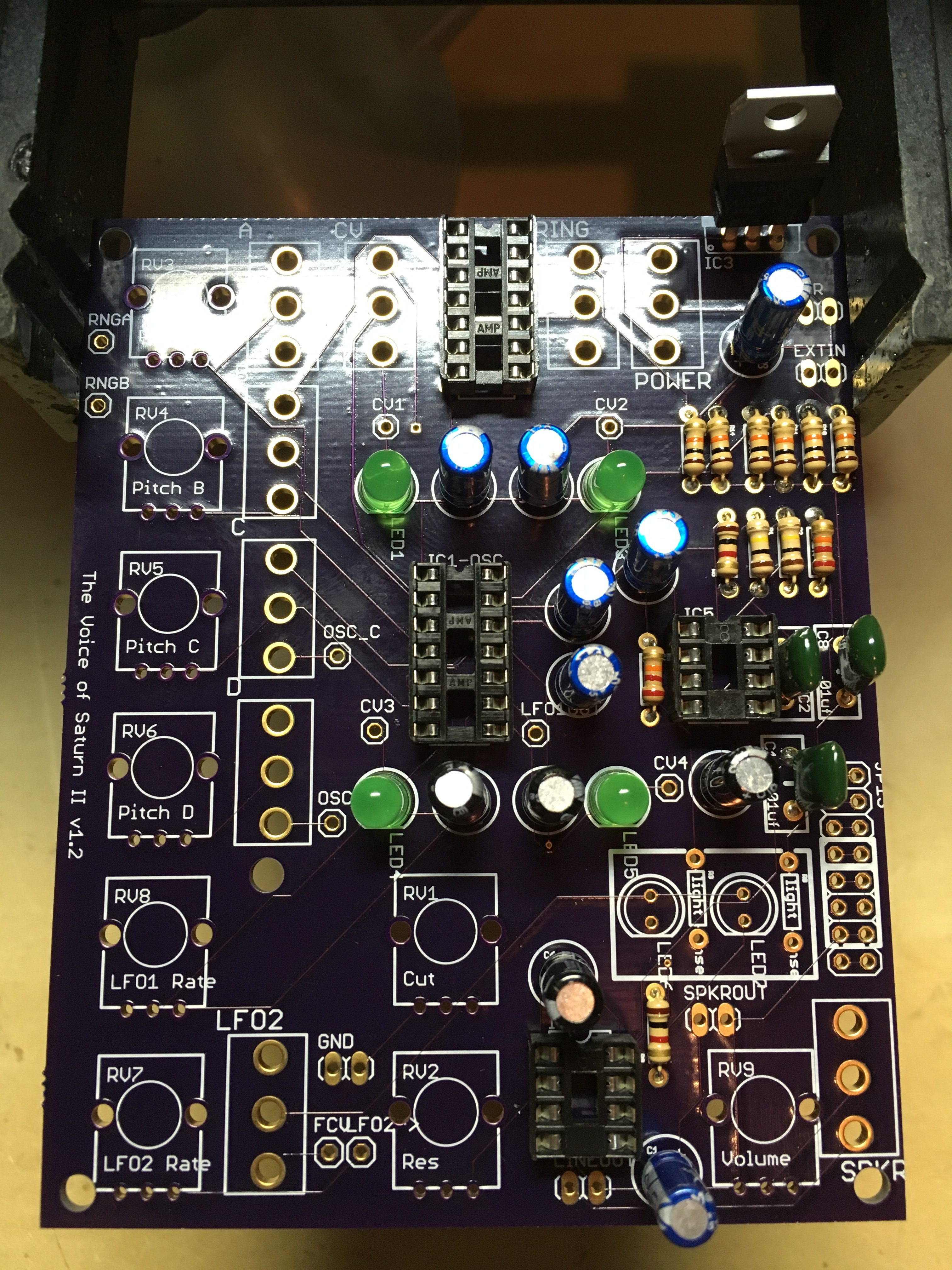
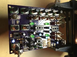
Now it is time for the LEDs. These are also polarized with the short leg going in the hole towards the flat edge of the silkscreen. First in stall the four in the middle of the board, then take a drink and make sure you’ve been cutting off those legs of all the components on the underside of the PCB. Save a few long ones for later! The image above shows an installed 5v voltage regulator. I’ve actually found that this thing works best on 9v and up to 12v. You can play with voltage starve circuits for even weirder fx (Google it!). On mine I jumpered pins 1 and 3 of the voltage regulator footprint to bypass it and just use the 9v from the battery or 12v with the eurorack version.
Maybe take a break and grab a nice cold beverage. Be careful not to spill it on your work area though. Maybe some fresh carrot sticks and hummus too? We’re about halfway there!
Step 4 – Vactrols What?!
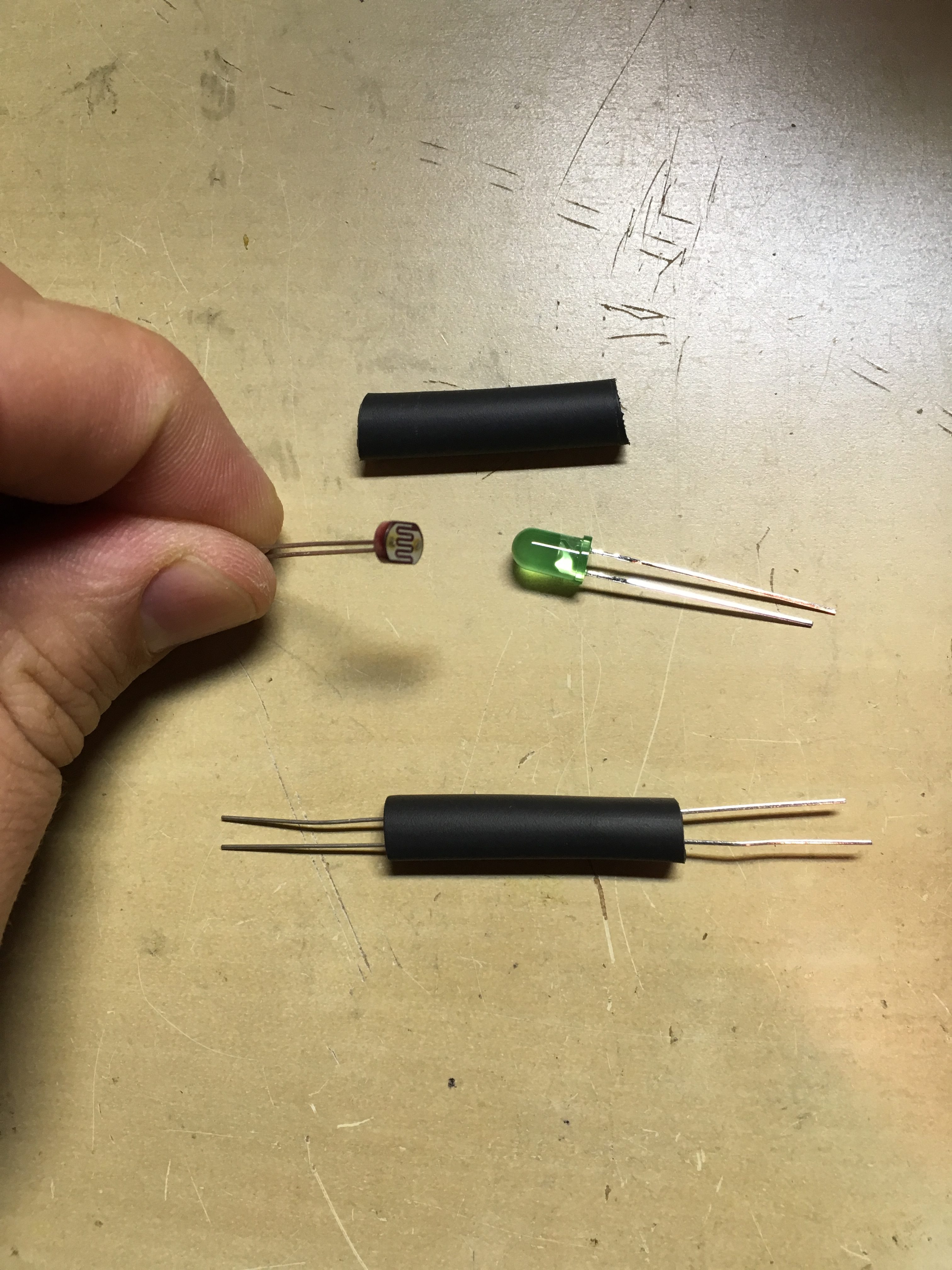
Without going into a ton of detail here is a quick way to make your own vactrol or LDR or voltage controlled resistor. This is the simple yet vaguely effective way the Voice of Saturn gets voltage control over its wonderful crusty filter. There’s two options here – you can make one yourself using a light sensitive resistor, LED and some heat shrink tubing as shown above, or you can get 2 Silonex nsl32 or similar commercially available packages .
The nsl32 types have a white dot which shows the side that the LED is on as well as the negative, shorter lead otherwise known as the cathode. The packaged vactrol/LDR type things tend to give a better range of control compared to the DIY ones but they are a bit more costly. I do recommend them and you can purchase them here! If you go the DIY route though, you can leave the heat shrink tubing loose (don’t heat it up) and then remove it to expose the light sensitive resistor and play the filter with a flashlight. You might be a weirdo too and that is completely okay with us!
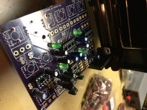
Here’s the DIY ones installed:
Step 5 – Potentiometers
Install the potentiometers (knob things). You might need to straighten out the side metal bits on them so they snap into the holes properly. Be careful to make sure they go in all the way and that the 3 pins in the front get through the holes properly. There’s several different values. Again, refer to the BOM to make sure you are putting them in the right place. The pots supplied with the kit have their values marked on them. Not the end of the world if you get it wrong. Also if you want to put this in your own enclosure and want to re-arrange things, just wire up panel mounted pots the way the board mounted ones would go – wiring the 3 pins to the three holes that are next to each other.
Step 6 – Switches
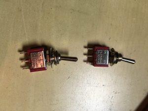
Now install the switches. There are 2 different types used in this guy:
One is the ON – ON type. This means the toggle either goes one way or the other and is used for PWR, RING SPKR, LFO2. The other type is ON – OFF – ON and is a 3 way toggle. The middle position means the switch connects nothing and is used for oscillators A, B, C, D, and the CV switch. For the oscillators these switches control routing or in the middle position turn the oscs off. For the CV switch it routes LFO 1 to modulate the pitch of either oscillator A or B or off in the middle position. The ring mod switch is kind of upside down in that if it is in the up position the ring modulator is disconnected from the output. The SPKR switch sends the sound to either the Line Out jumper or the Speaker Jumper through the LM386 amp. That can be used as a sound output as well but will be MUCH higher in volume so be careful not to blow your hifi!
Step 7 – Jump!
So apart from jacks, speaker and the battery snap you are done! Almost! There’s a few small jumpers to add an done resistor to add to correct some weirdness.
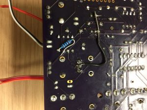
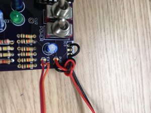
First the resistor. Without it the speaker kind of always makes some sort of noise no matter what because the input to the 386 is left kind of open. Not a huge deal for some, annoying to others. Just add a 1k resistor from pin 3 of the 386 to pin 4 (ground) like below (ignore the jumper wire above).
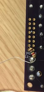
Or you can find an easier location for the 1k resistor if you are not using the eurorack power header. Just connect one side to the top pin of the speaker switch and the other side to the 2nd row in the header closest to the switch:
The next few jumpers are sort of choose your own adventure. There and pads included to add connections for modulating the other oscs with each other. You will see OSC_C and OSC_D which are outputs that send the signal of either of those two oscs out if their respective switch is in the up position. These can be connected to any of the Cv1-4 inputs. I recommend connecting OSC_D to CV3. If you connect a bunch of them you might blow the CD40106 chip. I haven’t verified this but I did blow some up at some point during development. I say go for it – the chips are inexpensive and thats why we have sockets! Just report back to me if you have problems.
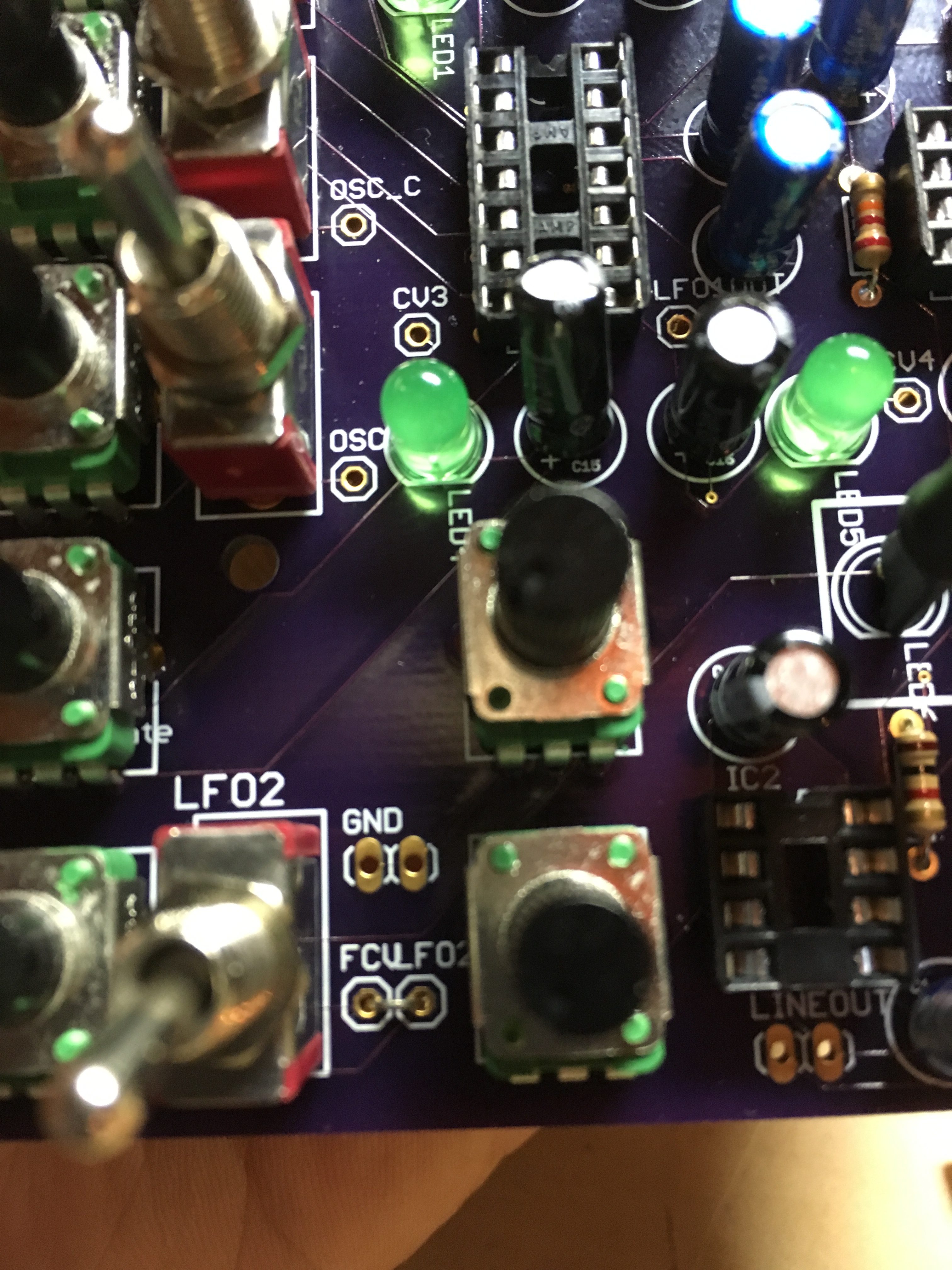
Next is the FCV / LFO2 business. If you aren’t going to use an external input for the filter control just jumper these two pads. If you want to use external cv control, like a trigger signal from a drum machine, or an LFO from a modular etc. I recommend using a switched jack with the LFO2 signal going to the switching tab and the F_CV going to the tip. There’s a hand ground pad provided for the ground!
Step 8 – Power, Jacks and Speaker!
Last bits! On the PWR, EXTIN, LINEOUT, SPKROUT pads, pad 1 is the signal and pad 2 is always ground. The EXTIN is an input to the resistor mixer for the filter and is experimental. It kinda works with some things but really only works best with another VoS Synth mkII. It likes its siblings I guess…
Step 9 – DO IT!
Okay! Now is the time to check your work, all your solder joints, trim wires, wash the pcb if you used that kind of flux/solder (if this sounds like another language, ignore for now), say some blessings, take some shots and, without the chips inserted power the thing up! If you don’t have a volt meter you can turn it off, put the chips in and take an extra shot. If you do – it is helpful to measure some voltages to make sure things are good to go. Theres some grounds on the jumper at the right of the board – which is also a eurorack compatible power header (for those that know/care). Find a ground and probe WITHOUT CHIPS INSERTED:
- IC5 PIN 8 – should read around 9v
- IC2 PIN 6 – should read around 9v
- IC1 PIN 14 – shoudl read around 9v
- IC4 PIN 14 – should read around 9v
When you insert the chips BE SURE TO PUT THE CHIP IN WITH THE NOTCH IN THE CHIP FACING THE NOTCH IN THE SILKSCREEN! Sorry for the bold caps, but that’s the one thing you can do to destroy all the chips. Don’t worry – again sockets rule!
Fire it up and make some noise! Coo your loved ones to sleep with the wondrous drones and blips and bleeps. Start your career as a famous EDM dj with a bangin’ donk! Or just connect it to a delay pedal and order a pizza. Please get in touch with problems, revisions and praise.
xox,
Travis
P.S. There’s a ton of theory not explained, like how the circuit works, what it does, etc. That will be here soon but I would like to thank the late Ray Wilson for his amazing designs and completely incredible and educational website. His contributions to the SynthDIY community are huge and I learned a lot through building his designs.
Legal things:

This work is licensed under a Creative Commons Attribution-NonCommercial-ShareAlike 4.0 International License.